Home > Math, Networking > Understanding spreading codes

Understanding spreading codes

Spreading codes as used in CDMA are binary-vectors that can be used to encode multiple binary streams to be sent over a  shared medium at the same time using the same carrier frequency. Sounds funky? It is! The secret is to use vectors which are mutually orthogonal. An easy mathematical way to create those is constructing Hadamard matrices as a base for the vectors, because it’s rows are orthogonal to each other.

Constructing those is surprisingly easy. You start with a matrix of order n and create a new of order 2n

H_{2n} =  \begin{pmatrix}  H_n & H_n \\  H_n & -H_n  \end{pmatrix}

A trivial Hadamard matrix is (1), lets expand it:
H_1=(1) \rightarrow  H_2=\begin{pmatrix}  1 & 1 \\  1 & -1  \end{pmatrix} \rightarrow  H_4=\begin{pmatrix}  1 & 1 & 1 & 1 \\  1 &-1 & 1 &-1 \\  1 & 1 & -1 & -1 \\  1 &-1 & -1 & 1 \\  \end{pmatrix}
H_4 allows 4 transmitters to simultaneously use the medium. To achive this you must encode each data stream. This is done by multiplying the data segment with the code. E.g: Sending 1011 =(1,-1,1,1) using code (1,-1,-1,1) becomes (1,-1,-1,1,-1,1,1,-1,1,-1,-1,1,1,-1,-1,1). If you’re represent the negatives as zeros, this becomes a simple bitwise AND-operation.

CDMA sample coding

Now what happens if multiple emitters try to transmit this at the same time? This is where the fancy math comes into play. Orthogonal vectors form a right angle in space. We have 4-dimensional vectors UMTS uses 512-dimensional vectors, so don’t try to picture it :) – instead think about what you know about dot products of vectors:

\overrightarrow{v_1} \cdot \overrightarrow{v_2} = |\overrightarrow{v_1}||\overrightarrow{v_2}|\cdot cos(\alpha)
Where \alpha is the angle formed by the vectors.

As cos(90°) is 0, the dot product becomes 0 for orthogonal vectors.

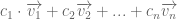
When you send information at the same time, the carrier waves interfere with each other therefore the sending process of multiple transmitters could be described as follows (the different c_ns represent differences in transmitting power):

c_1 \cdot \overrightarrow{v_1} + c_2 \overrightarrow{v_2} + ... + c_n \overrightarrow{v_n}
Because the vectors are mutually orthogonal the reciever only has to dot-multiply the signal with the desired channel vector. All other subtotals become 0.

E.g: S1 sends 11 and uses code (1,-1,-1,1), S2 sends 10 and uses code (1,1,1,1),

S1:  \begin{array}{rrrrrrrrr}  & 1 & 1 & 1 & 1 & 1 & 1 & 1 & 1 \\  \cdot & 1 & -1 & -1 & 1 & 1 &-1 &-1 & 1 \\  \hline  = & 1 & -1 & -1 & 1 & 1 &-1 &-1 & 1  \end{array}

S2:  \begin{array}{rrrrrrrrr}  & 1 & 1 & 1 & 1 & 1 & 1 & 1 & 1 \\  \cdot & 1 & 1 & 1 & 1 &- 1 &-1 &-1 & -1 \\  \hline  = & 1 & 1 & 1 & 1 &- 1 &-1 &-1 & -1  \end{array}

Sum:  \begin{array}{rrrrrrrrr}  & 1 & -1 & -1 & 1 & 1 &-1 &-1 & 1 \\  + & 1 & 1 & 1 & 1 &-1 &-1 &-1 & -1 \\  \hline  = & 2 & 0 & 0 & 2 & 0 &-2 &-2 & 0  \end{array}

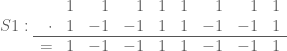
The reciever doesn’t need the exact results of this, aslong as the signs preserve he can extract the the desired channel by dot multiplication:
First bit S1:
\begin{pmatrix}  2 \\  0 \\  0 \\  2  \end{pmatrix} \cdot    \begin{pmatrix}  1 \\  -1 \\  -1 \\  1  \end{pmatrix}    = 2 \cdot 1 + 0 \cdot -1 + 0 \cdot -1 + 2 \cdot 1 = 4

Second bit S2:
\begin{pmatrix}  0 \\  -2 \\  -2 \\  0  \end{pmatrix} \cdot    \begin{pmatrix}  1 \\  1 \\  1 \\  1  \end{pmatrix}    = 0 \cdot 1 + -2 \cdot 1 + -2 \cdot 1 + 0 \cdot 1 = -4

As you can see positive results represent logical ones and negative represent logical zeros. The result is gained by the dimension (length) of the code vector. This is a nice sideeffect of CDMA as in practice this means you can use significant lower emiting power.

Categories: Math, Networking
  1. No comments yet.
  1. No trackbacks yet.

Leave a comment